
U4S2_AI/12_ANA
The ADC-400A/12 card provides 12 stereo analog audio inputs for external audio signals that can be used for a small amount of audio routing. Each stream provides conversion from analog audio to AES or AES to analog audio, making this module perfect for switching mixed audio formats without requiring external conversion. When the audio submodule is present, the analog audio is switched as mono streams for added flexibility for embedding the signal into the video stream or sending it to MADI or AES outputs. Balanced connections are available. Optional balanced breakout panels are available to convert Sub-D connectors to a terminal block.
Find Your Sales Rep
Check the map below to see your sales representative’s contact information.
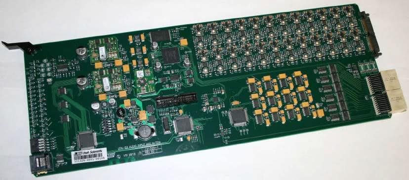
The ADC-400A/12 Digital Audio ADC Input with TDM Board (121325-1) receives 12 L/R analog signals. These signals are received and individually converted into AES3 signals that are aligned to the digital audio reference (DARS). In its standard form DARS is an AES3, 48 kHz signal with sample and frame rate information. These input boards provide a TDM stream and 12 separate AES3 signals to the system crosspoint for routing.
Circuit Description
The analog audio input signals arrive as differential pairs and are sampled and converted in to data. They are then presented to an FPGA that evaluates and aligns them with clock and sync signals derived from the DARs input.
If there is no DARs present, the input signals will be sampled at 48kHz and the audio data will be aligned using the fallback oscillator. The audio payload is converted back into AES3 and passed to the system xpoint in two methods. One method includes individually passing the 12 AES3 signals to the system xpoint and the other method includes a single TDM stream that carries all 12 inputs information. The system xpoint will determine whether it uses the TDM or Non-TDM inputs.
Controls and Indicators
Controls:
P1 Standard UT400 diagnostic port provides detailed operational status and control for this card.
Indicators:
COMMS > Communications indicator (Yellow). Illuminated when the Frame Controller Module addresses this card.
PWR OK > Power supply indicator (Green). Illuminated when the local power supplies are within tolerance.
SIGDET(L/R)1-12 > Signal detection LEDs (Green). Illuminated when a non-silent audio signal is detected on the associated receiver input.
1.2V, 1.8V, 2.5V, 3.3V, 5VA, 12V, and -12V > Power supply fail indicators (Red). Illuminated when local voltages fall out of 5% tolerance.


