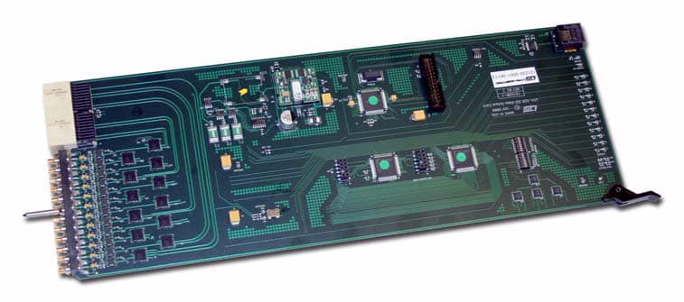
HO3-400/12
The HO3-400/12 card provides 12 outputs for SDI formats, supporting signals from 3Mbps all the way up to 3G including SD-SDI, HD-SDI, 3G-SDI, dual- or quad-link 4K, and DVB/ASI. Reclocking is provided as standard for the best possible signal quality on all SMPTE-standard formats.
Find Your Sales Rep
Check the map below to see your sales representative’s contact information.
The HO3-400/12 Multi-rate Output card is used to drive single ended data signals out of the router. It has integral Clock and Data Recovery circuits that operate on standard SMPTE Video frequencies and work to remove jitter from the signal. The cards also contain high quality, high capability cable driver components that allow them to drive long lengths of coax cable.
Circuit Description
Signals enter this card from multiple crosspoint cards. The control signals from the Frame Communication module determine whether the output stage selects signals from the Primary or Redundant Crosspoint cards.
Once an input is selected, the output stage typically reclocks it unless the signal is not a standard SMPTE video frequency, and then the signal is bypassed.
After the signal passes through the reclocker stage, it is presented to the cable driver stage which generates a signal centered around 0V with an amplitude of 800mV. The rise and fall time of these signals will adhere to the SMPTE specification for the signal type, or default to a 200pSec rise time if the signal type is non-standard.
Controls and Indicators
Controls:
– This card has a two-bank dipswitch with a total of 16 switches. 12 of them are used to force a bypass condition on each of the 12 individual outputs (Labeled as P1-P12).
The other four dipswitch locations should remain placed toward their labeling on
the PCB.
– P1 is a standard UT400 diagnostic port that provides detailed operational status and control for this card.
Indicators:
– Communications indicator – Yellow. Illuminated when the card has been addressed by the Frame Controller Module.
– PS Fail LED. – Red – Illuminated when the 3.3V power supply falls out of +5% tolerance.
– Reclocker Locked LEDs (12) – Green. One of these LEDs is present on the front edge of the card for each input signal. They are labeled as ‘Locked’ 1-12. It is important to note that if the reclocker is bypassed, either manually or automatically, signal could still be passing through the output if the LED is OFF.
– Redundancy selection LEDs (2) – These are two LEDS nearest the edge connector of the card that indicate which crosspoint the card is getting signal from. DS15 is labeled P/R and indicates that the card is receiving signals from its redundant crosspoint when it is illuminated. DS16, labeled as N/I, indicates that output 0 of the card is receiving signals from its Mezzanine Level redundancy crosspoint card.